Friday, 6 April 2012

Bending...


Both metal, and the rules :-)

But more of that later...  First of all, this is how the saddletank has gone together so far.  It's a very clever design idea.  First you build a stout subframe that will keep everything square, and then you put the top and sides in place.  These are held in place with etched tabs whilst you solder it together, and then file the tabs off after all is done.

This is the subframe assembled with the panel of the tank top already in place.  This is located over vertical tabs which have been filed off leaving just the faintest of traces.


The horizontal tabs are left in place as they are used to locate the side panels of the tank.

This is the tank subframe from underneath.  The plate with all of the holes in it acts as a reinforcing piece for the assembly.  The multitude of holes is to enable you to easily solder it in place.  I used an RSU to join them together, so it was less relevant for me, but if you are using a conventional iron, then you can flood solder through the holes.


Now this is where I started bending the rules, as well as the metal.  Normally Chris's instructions in High Level Kits are absolutely spot on, and indeed they come with a sizeable health warning not to alter them and try to do your own thing.

However when it came to shaping the complex S-curve  that makes up the sides of the tank, I felt a little nervous.  The instructions state that you should anneal the panels prior to bending them.  I'm never comfortable at my ability to anneal brass evenly, and to the right extent.  Added to the facts that the panels themselves are already half-etched, and that I was not confident that the completed sides would not accidentally pick up dents in the softened metal, and alternative approach was needed.

So I started off by putting the gentle curves at the top of the tank in by pressing the metal around a largish diameter metal rod on to the mouse mat on my desk.  Then I clamped the panel against the rod in my modelling vice, and used a further rod to gently ease it over, as in these pictures...


You can also see the gentle bend that I put in at the top of the tank from the pressure on the mouse mat.

Well, this may not be the recommended way to form the curves in the tank but I seem to have got away with it.  This is the first panel fitted into place on the tank, and held in place only by the locating tabs.


I've now done the second side panel as well, and maybe later tonight I'll get chance to solder them in place.

Flymo


Great balls of solder...


Or rather, very tiny ones...

After the arrival of my vials of solder from Hong Kong, I couldn't wait to try them out.


This is the top of the saddletank of the Coffeepot about to be soldered into place.

- position parts for soldering on the RSU (which is why it is all silvery - that is tin foil used as the negative terminal)
- apply spot of flux using pipette bottle
- apply single 0.7mm ball of solder using tweezers
- place RSU probe, and press [on] switch

Zap...  and a very neat join with no cleaning up required.  I like this :-)

If anyone else is thinking of ordering these solder balls, I'll just confirm that for 4mm, the 0.7mm size seems just right.  Anything smaller is just too damn fiddly to manipulate easily, although I can see that "pouring" them into place will work well in certain circumstances with the very smallest size.

Flymo

Wednesday, 4 April 2012

The right tool...


Every so often, having the correct tool for the job makes life so much easier.

The otherwise excellent instructions from High Level for their Coffee Pot kit refer to using a piece of wood to bend the inner of the saddle tank squarely up.  Or you can do as I did and use a Hold-And-Fold tool.  


Very easy, very accurate, and you should get perfect straight bends.  It's one of those "investment tools" that you don't use every day, but when you do, you reflect on just how easy it makes things...

Flymo

Monday, 2 April 2012

Eastern promise


One of the joys of the internet is that it makes all sorts of things available to you from all sorts of sources, that you possibly never even knew existed before...

When returned on Friday from a business trip to Singapore, I found a package waiting for me...


Lots of pretty coloured stamps on the outside!  It was the contents of it that I was really interested in.

First up was a set of electronic tweezers.  These (apologies for the rather blurred shot) are unusual in that they have plastic tips on them so that they don't short out electronic components. I was curious what they would be like.  


They don't have as fine a point as I expected.  However the fact that the tips are made out of plastic will make them very useful when I file grooves in the ends of them to pick up what came out of package next...


These are an assortment of small - that is a one pound coin for size comparison - glass vials containing balls of solder.  I went for a "trial pack" which contains different size balls of sizes 0.75mm, 0.45mm and even 0.3mm.  And there are 10,000 of each size in each vial!

When I saw these, I was amazed at the possibilities for really precision, clean soldering either using a conventional iron or more likely an RSU.  These offer a really precise way to get as much or as little solder in the joint as you wish.  I have no idea what they are used for in the electronics industry, yet to me they offer lots of possibilities.

And finally to the real reason why I had been browsing on Ebay:


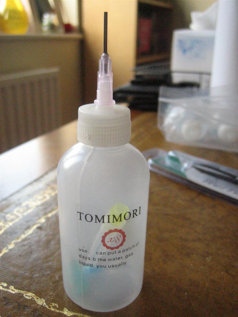
Small pipette bottles.  For the last couple of years, Tim Watson has used these during his soldering tutorial at Missenden to hold flux.  They allow it to be dispensed in a much more precise way than the traditional mucky paintbrush.  Even Tim says that these are getting more scarce for him to find through his chosen trade of dentistry, so I thought that I'd have a look and see what the internet could throw up.

These cost not-a-lot each, and I got four of them.  Each one comes with a variety of different sized nozzles so I'll see what gives the best control.  And they should be a lot less messy when the inevitable happens and they get knocked over on the workbench!

What was perhaps even more impressive was that I ordered these last Sunday before I left, and they were waiting for me on Friday when I returned home.  That's a turnaround time that many dommestic businesses can struggle to meet.  It just reflects the impeccable service culture that I have found all over Asia. 

Flymo

Saturday, 24 March 2012

An early start on my Y5


An early start to Saturday morning - all of those years of 6am alarm calls means that I find it impossible to stay asleep at weekends - saw me heading to the workbench for some soldering before the rest of the household woke. 

Fortified with a strong coffee, my first task was to finish soldering the cab wrapper in place from where I left off last night.  This was soldered in place around the seams, and the edges cleaned up.  It's an almost perfect fit, with just a tiny excess around the edge to enable you to get it properly centred and fixed, and then a few strokes of the file mean that the base layer and the overlay are visually one.

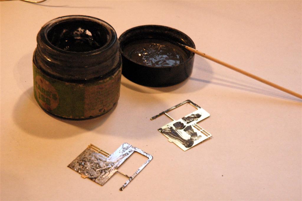
After this, it is the cab sides - again in the form of overlays.  In this case, I'm using my RSU to put them in place.  It enables a really neat finish, and very controlled soldering.  The first step, after removing the parts from the fret and cleaning off the (minuscule) tags, is to tin them.  Here I'm using a thin layer of 188 solder paint, and wiping it on with a conventional iron.


High Level Kits make plentiful use of locating tabs to help you put everything together correctly, and in the right place.  In this case, there is a convenient slot in the footplate that takes the tab that is just visible at  the bottom of the cabside.  I took two steps to help ensure that the parts located snugly:

- clean back any excess solder from the right-angle where the cab base layer meets the footplate so that the overlay can fit all the way down.  This was done with the back of a scalpel blade as a scraper, then finished off with a fibreglass pencil

- ensure that the tab is slightly chamfered - a few gentle strokes with a file and nothing more - to enable it to enter into the slot easily.

Then it was the use of the RSU to work carefully around the cabside to put it into place, avoiding working to quickly so that there was no heat build-up and distortion.


Just visible in the front bottom corner of the overlay is a spot of solder that I used as a tack to ensure that the piece didn't move before I started using the RSU.  This was then easily cleaned off once everything was securely in place.

Now on to the bunker fronts... And breakfast!

Flymo


Friday, 23 March 2012

Soldering again...

For the first time since Missenden, I have the chance to do some modelling :-)

This is how the body of my "Coffeepot" was left at the end of the weekend:


Although it looks like a nasty accident has befallen the cab, it is actually supposed to be that way.  Chris has designed a very clever way of accurately building the kit that uses a sub-frame over which a wrapper for the cab front, roof and rear is put into place.

It all locates using slots and tabs, and the only tricky bit is bending the curves at the front and rear of the roof.  Even this gets a good tip from Chris - he suggests using a very feint scribed line on the outside of the bend so that the curve is made in the correct place - and he even etches reference marks on the fret to make sure that you get them in the right place...

So this is where I'll be starting from.  Hopefully more pictures to show progress tomorrow!

Cheers
Flymo


Saturday, 10 March 2012

Missenden 2012

And off for a weekend's modelling at Missenden Abbey :-)

Friday night saw the traditional setting up of workbenches and unpacking of kits.  This is my travelling ensemble:


And the kit that I will be making - a High level Y5 GER 0-4-0.  Note printed pictures from the web that I can then scribble on to highlight the detailing that I need.


Friday night is also a time to meet up with old friends.  My group includes David Brandreth , John McAleely from my Area Group CHEAG, and Mark Tatlow (of Portchullin fame).  Here is Mark looking for a place to call his own.


Then after a spot of dinner (fish and chips, with it being Friday) it was down to a couple of hours modelling.  And at the end of it, I had a laminated footplate (all done with a resistance soldering iron - thank you London Road Models) and a set of splashers.  You wouldn't think it, but even with such small parts, using a set of GW Models rolling bars made forming the splashers really easy.


 And that's progress so far!  Now I'm wasting valuable modelling time, so more later...

Flymo